Constituent elements of the DP system shall be called as components and systems, as besides the unit itself (sensor, generator, thruster), there are wires, switches, piping, valves, etc. That is why the unit and everything required for its functioning shall be referred as a ‘component’, where the word ‘system’ shall be used for the DP system and power management system.
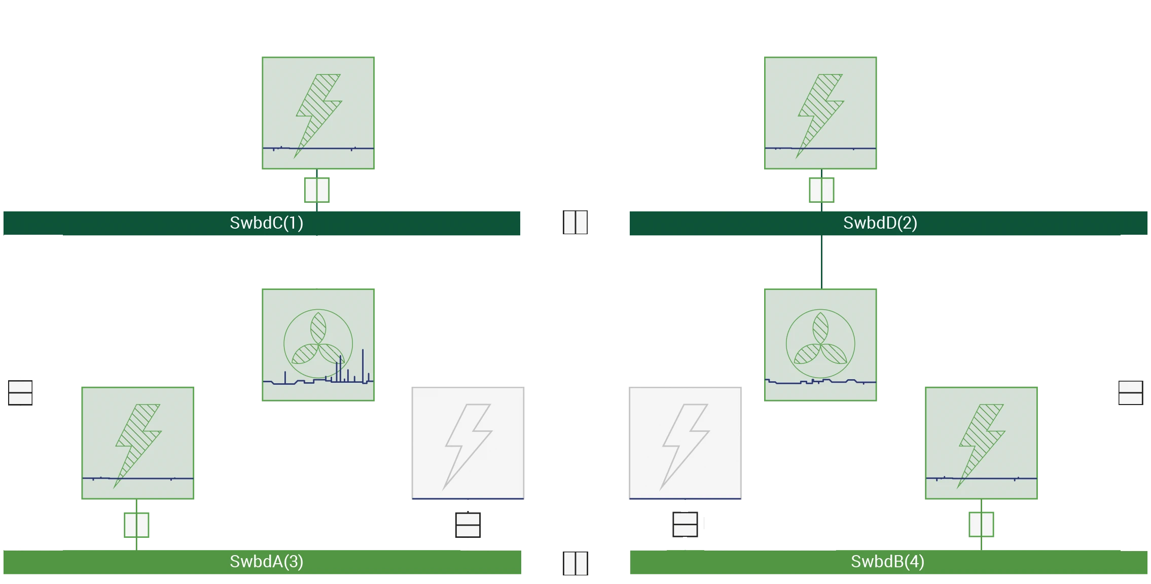
DP class 1 system does not require power redundancy. DP class 2 system is provided with it, that is why the Power system is divided into two buses,. It shall be divided in such a way, to supply enough power for position keeping in case of the worst-case failure. Meanwhile, the power system(s) may be run as one system during operation, if the bus-tie breaker is fitted, that will separate the buses in case of a failure (overload or short circuit).
Power system means all components and systems necessary to supply the DP system with power. The power system includes but is not limited to:
1 prime movers with necessary auxiliary systems including piping, fuel, cooling, pre-lubrication and lubrication, hydraulic, pre-heating, and pneumatic systems;
2 generators;
3 switchboards;
4 distribution systems (cabling and cable routeing);
5 power supplies, including uninterruptible power supplies (UPS);
6 power management system(s) (as appropriate).

In the event of blackout, there is an Uninterruptable Power Supply, that will provide the operation of the controller, console, sensors and position reference systems with the power for a minimum of 30 minutes. DP class 2 system has got two UPSs, while DP class 3 system has got three. To provide redundancy, each UPS supplies power to an individual console, controller, group of sensors and position reference systems, without being dependent on other UPS.
It is necessary to mention, that there are no requirements for the installation of the Power Management System (PMS) on board according to Circular 645. However, if such a system is installed, it shall be reliable and shall comply with the requirements of the Administration. Indeed, the power management system is installed on many DP class 2 and DP class 3 vessels built before 2017, as it was required by the Classification Societies. Circular 1580 contains the requirement for DP class 2 and DP class 3 vessels to have power management system on board.
Power management system supplies power, when it is necessary, and prevents blackout on the vessel. Power management system includes such equipment as engines, generators, switchboards and control panels along with the automation equipment that performs the calculation algorithms.
Power Management System objectives:
- Controlling the load and preventing overload (Blackout Prevention function);
- Reducing the load and disconnecting some particular consumers, when it is necessary, e.g. providing thrusters with the extra power needed for position keeping by switching off the vessel’s air conditioner (Preferential Tripping function);
- Controlling the load of individual generators and overall power capacity;
- Sharing the load equally among generators (Share Load function);
- Monitoring available power at present (spinning reserve) and, whether it is necessary, to connect more generators for starting a heavy consumer (Heavy Consumer Blocking function);
- Starting generators and thrusters automatically after a full or partial loss of power on board (Blackout Recovery function).
While projecting power management system, it is necessary to consider power characteristics of the system components, including critical equipment failure and to provide constant protection of other systems despite of these malfunctions.
src: estumar.com


